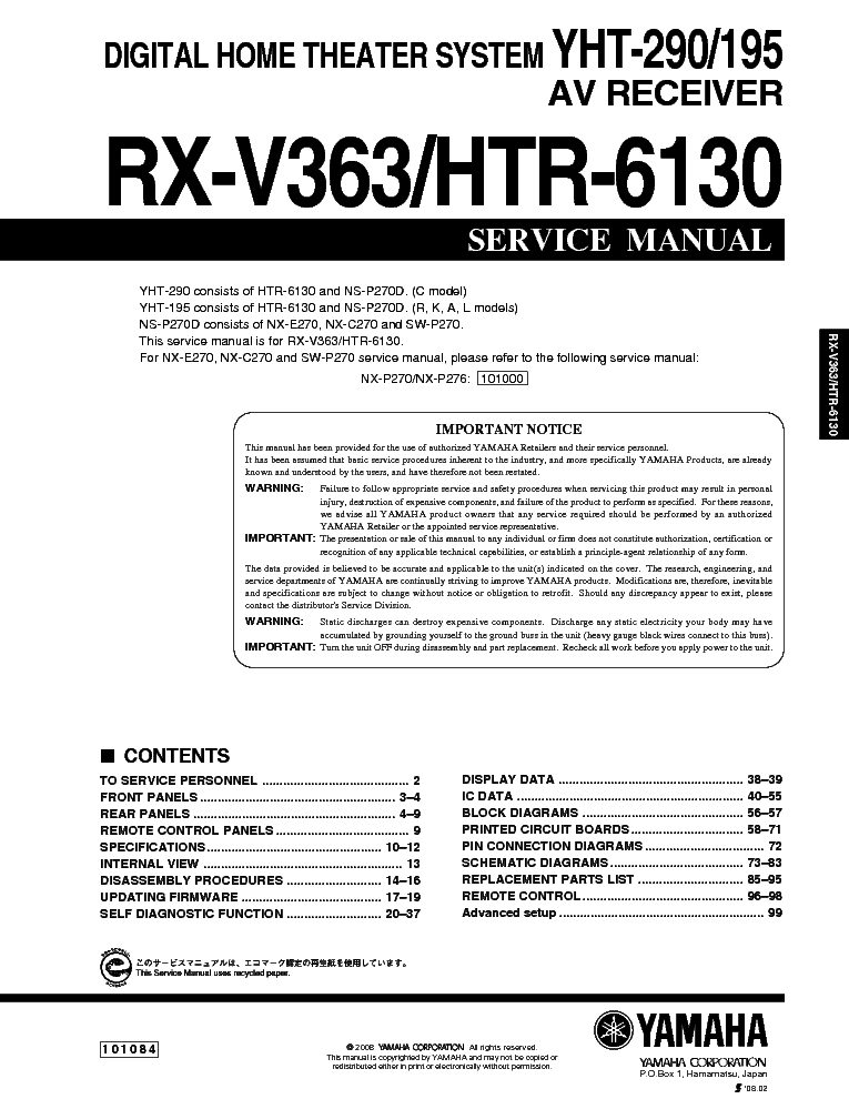
Инструкция Yamaha Rx V363


Tuning range: FM, MW. Power output: 100 watts per channel into 8Ω (stereo). Surround output: 100W (front), 100W (center), 100W (rear). Frequency response: 10Hz to 100kHz. Total harmonic distortion: 0.9%. Input sensitivity: 200mV (line). Signal to noise ratio: 100dB (line). Channel separation: 45dB (line). Manuals and user guide free PDF downloads for Yamaha RX-V363 - AV Receiver.
USING BLUETOOTH™ COMPONENTS 41 En English BA S IC OPERA T ION You can connect a Yamaha Bluetooth adapter (such as YBA-10, sold separately) to the DOCK terminal of this unit and enjoy the music contents stored in your Bluetooth component (such as a portable music player) without wiring between this unit and the Bluetooth component. You need to perform “pairing” the connected Bluetooth adapter and your Bluetooth component in advance.
Pairing must be performed when using a Bluetooth component with the Bluetooth adapter connected to this unit for the first time or if the pairing data has been deleted. “Pairing” refers to the operation of registering a Bluetooth component for Bluetooth communications. Y • You only need the pairing operation for the first time that you use the Bluetooth component with the Bluetooth adapter. • Pairing requires operations on this unit and on the other component with which Bluetooth communications are to be established. If necessary, refer to the other component’s operating instructions. There are two pairing methods: pairing by using “START PAIRING” in “SET MENU” and quick pairing. ■ Pairing by using “SET MENU” Use this feature to perform pairing with the video monitor.
Select “START PAIRING” in “INPUT MENU”. See page 50 for details. ■ Quick pairing 1 Press 4 AMP and then press NINPUT l / h repeatedly (or press 3 V-AUX/DOCK ) to select “V-AUX” as the input source. 2 Turn on the Bluetooth component you want to pair with. 3 Press and hold C BAND (or 6BAND ) for 3 seconds. Once the Bluetooth adapter starts pairing, “Searching.” appears for a moment. While the Bluetooth adapter is in the pairing mode, DOCK indicator flashes in the front panel display.
Y To cancel the pairing, press C BAND (or 6 BAND) again. If the Bluetooth adapter is not connected to the DOCK terminal of this unit, “No BT adapter” appears in the front panel display. 4 Check that the Bluetooth component detects the Bluetooth adapter. If the Bluetooth component detects the Bluetooth adapter, “YBA-10 YAMAHA” (example) appears in the Bluetooth device list. 5 Select the Bluetooth adapter in the Bluetooth device list and then enter the pass key “0000” to the Bluetooth component.
When the pairing procedure is successful, “Completed” appears in the front panel display. The Yamaha Bluetooth adapter can be paired with up to eight other components. When pairing is conducted successfully with a ninth component and the pairing data is registered, the pairing data for the least recently used other component is cleared. 1 Press 4 AMP and then press NINPUT l / h repeatedly (or press 3 V-AUX/DOCK ) to select “V-AUX” as the input source. 2 Start playback of your Bluetooth component. When the connected Bluetooth adapter detects the Bluetooth component, “BT connected” and the DOCK indicator appears in the front panel display. Y • When you press 7 ENTER on the remote control, the connected Bluetooth adapter searches and connect to the last connected Bluetooth component.
If the Bluetooth adapter cannot find the Bluetooth component, “Not found” appears in the front panel display. • To disconnect the Bluetooth adapter from the Bluetooth component, press 8 RETURN.
Using Bluetooth™ components Pairing the Bluetooth™ adapter and your Bluetooth™ component To ensure security, a time limit of 8 minutes is set for the pairing operation. You are recommended to read and fully understand all the instructions before starting. Note Note Playback of the Bluetooth™ component 01EN_RX-V363_U.book Page 41 Friday, December 7, 2007 5:44 PM Black process 45.0° 240.0 LPI.
• This manual has been provided for the use of authorized YAMAHA Retailers and their service personnel. It has been assumed that basic service procedures inherent to the industry, and more specifically YAMAHA Products, are already known and understood by the users, and have therefore not been restated. • RX-V363/HTR-6130 I TO SERVICE PERSONNEL 1. Critical Components Information AC LEAKAGE Components having special characteristics are marked s and WALL EQUIPMENT TESTER OR OUTLET UNDER TEST EQUIVALENT must be replaced with parts having specifications equal to those originally installed. Leakage Current Measurement (For 120V Models Only) • RX-V363/HTR-6130 I SPECIFICATIONS I Audio Section Tone Control Characteristics Minimum RMS Output Power (Power Amp. Section) BASS (1 kHz, 0.9% THD) Boost/Cut.±10 dB (100 Hz) FRONT L/R, CENTER, SURROUND L/R TREBLE U, C models (8 ohms).100 W/ch Boost/Cut. AC 240 V, 50 Hz DVD Live Viewing Music Live MUSIC Pop/Rock SYSTEM B, G, E, F models.AC 230 V, 50 Hz “SILENT CINEMA” is a trademark of Yamaha Corporation.
DVR Viewing MOVIE Movie Dramatic SYSTEM Power Consumption Music Disc Listening. • RX-V363/HTR-6130. • RX-V363/HTR-6130 I INTERNAL VIEW Power Transformer OPERATION (3) P.C.B.
OPERATION (5) P.C.B. (R, L models) MAIN (3) P.C.B. Tuner HDMI P.C.B. OPERATION (4) P.C.B. MAIN (4) P.C.B. MAIN (1) P.C.B.
OPERATION (2) P.C. Download My Little Pony Dublat In Romana. B. OPERATION (11) P.C.B. OPERATION (6) P.C.B. • RX-V363/HTR-6130 I DISASSEMBLY PROCEDURES (Remove parts in the order as numbered.) Disconnect the power cable from the AC outlet.
Removal of Top Cover a. Remove 4 screws (1), 4 screws (2) and 1 screw (3). Slide the top cover rearward to remove it. • RX-V363/HTR-6130 3. Removal of HDMI P.C.B.
Remove CB904 and CB905. Remove 5 screws (5). Remove HDMI P.C.B. Removal of OPERATION (4) P.C.B. Remove CB193 and CB182. Remove 7 screws (6).
• RX-V363/HTR-6130 When checking the P.C.B. Remove the Top cover. Remove 3 screws (8). Remove 5 screws (A) and 4 screws (B). Place the P.C.B.s (with rear panel) upright.
• RX-V363/HTR-6130 I UPDATING FIRMWARE After replacing the following parts, be sure to write the latest firmware. • IC201 (DSP P.C.B.) G Required Tools G Operation Procedures • DVD or CD player (with DIGITAL OUTPUT (OPTI- 1. Connect this unit and DVD/CD player as shown be- CAL or COAXIAL) jack) low. • RX-V363/HTR-6130 2. While simultaneously pressing the “STANDBY/ON” and “SPEAKERS A/B/OFF” keys of this unit, connect the power cable of this unit to the AC outlet.
2) The FIRMWARE UPDATE mode is activated and “SPDIF Upgrade” is displayed. 2) 'STANDBY/ON'. • RX-V363/HTR-6130 When the version of the firmware to be written is the same as the one existing in this unit, “Same Version”, “Please.” and “Turn off!!” are displayed repeatedly. (Upgrading is not necessary.) If the display remains unchanged for more than 10 seconds after starting the firmware CD play procedure, per- form the firmware CD play procedure again from the beginning. • RX-V363/HTR-6130 I SELF DIAGNOSTIC FUNCTION This unit has self diagnosis functions that are intended for inspection, measurement and location of faulty point.
There are 14 main menu items, each of which has sub-menu items. Listed in the table below are menu items and sub-menu items. • RX-V363/HTR-6130 Main menu Sub-menu PROTECTION HISTORY History 1 History 2 History 3 History 4 iPod DOCK: xxx DOCK ignore SOFT SW SW MODE MODEL DESTINATION TUNER DESTINATION VIDEO FORMAT YPAO DOCK (iPod) FACTORY PRESET PRESET INHI PRESET RSRV ROM VER/SUM. • RX-V363/HTR-6130 • Starting Self-diagnostic Function Press the “STANDBY/ON” key while simultaneously pressing those two keys of this unit as indicated in the figure below. Keys of this unit Turn on the power while pressing these keys. • Starting Self-diagnostic Function in the protection cancel mode If the protection function works and causes hindrance to trouble diagnosis, cancel the protection function as described below, and it will be possible to enter the self-diagnostic function mode. • RX-V363/HTR-6130 When there is no history of protection function: When there is no protection history After a few seconds NO PROTECTION 1.ANLOG BYPASS When there is a history of protection function due to excess current PRI PRT:xxx AD value when the protection function is working Cause: An excessive current flowed through the power amplifier.
• RX-V363/HTR-6130 When there is a history of protection function due to abnormal voltage in the power supply section PRV PRT:xxx AD value when the protection function is working Cause: The voltage in the power supply section is abnormal. Supplementary information: The protection function worked due to a defect or overload in the power supply. • RX-V363/HTR-6130 • Operation procedure of Main menu and Sub-menu There are 14 menu items, each of having sub-menu items. Main menu selection: Select the menu using “>” (forward) and “.